DISCOM Net Metering Application Checklist: SLD, Site Plan, Earthing Layout and Documents
A practical checklist of the drawings and documents Indian DISCOMs typically need for rooftop solar net metering and PM Surya Ghar — what a good single-line diagram, site plan and earthing layout contain, and the most common reasons files get sent back.
Rooftop solar in India isn't finished when the last module is clamped down. Before the system can export, the DISCOM has to approve the connection, inspect the installation and install or test the net meter — and under PM Surya Ghar, the subsidy is only released after inspection. Every one of those steps depends on documents and drawings. A clean, consistent file moves through quickly; a file with a missing protection device on the SLD, a capacity that doesn't match the application, or module serial numbers that don't match the DCR certificate comes back for rework, sometimes more than once.
This guide is a checklist of what DISCOMs typically need, what each drawing should contain, and the mistakes that cause most rejections.
Requirements vary by state
Every state and DISCOM has its own forms, portal steps and technical requirements, and they change. Use this guide as a structure, and always check your DISCOM's current checklist and the PM Surya Ghar national portal (pmsuryaghar.gov.in) for the latest rules.
The approval journey at a glance
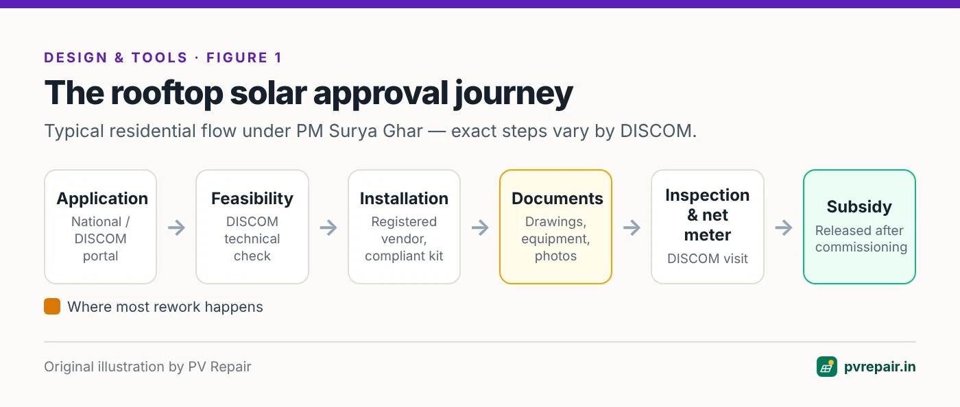
For a typical residential system under PM Surya Ghar, the process runs roughly as follows:
- Application on the national portal (and/or the DISCOM portal), with consumer details and the proposed capacity.
- Technical feasibility — the DISCOM checks that the connection, transformer and sanctioned load can accommodate the system.
- Installation by a registered vendor using compliant equipment.
- Document upload — installation details, drawings, equipment details and photos.
- Inspection and net meter installation or testing by the DISCOM.
- Commissioning, followed by subsidy release to the consumer's bank account.
Commercial and industrial systems follow a similar path through the DISCOM's net metering or gross metering process, usually with more detailed drawings and approvals.
The document checklist
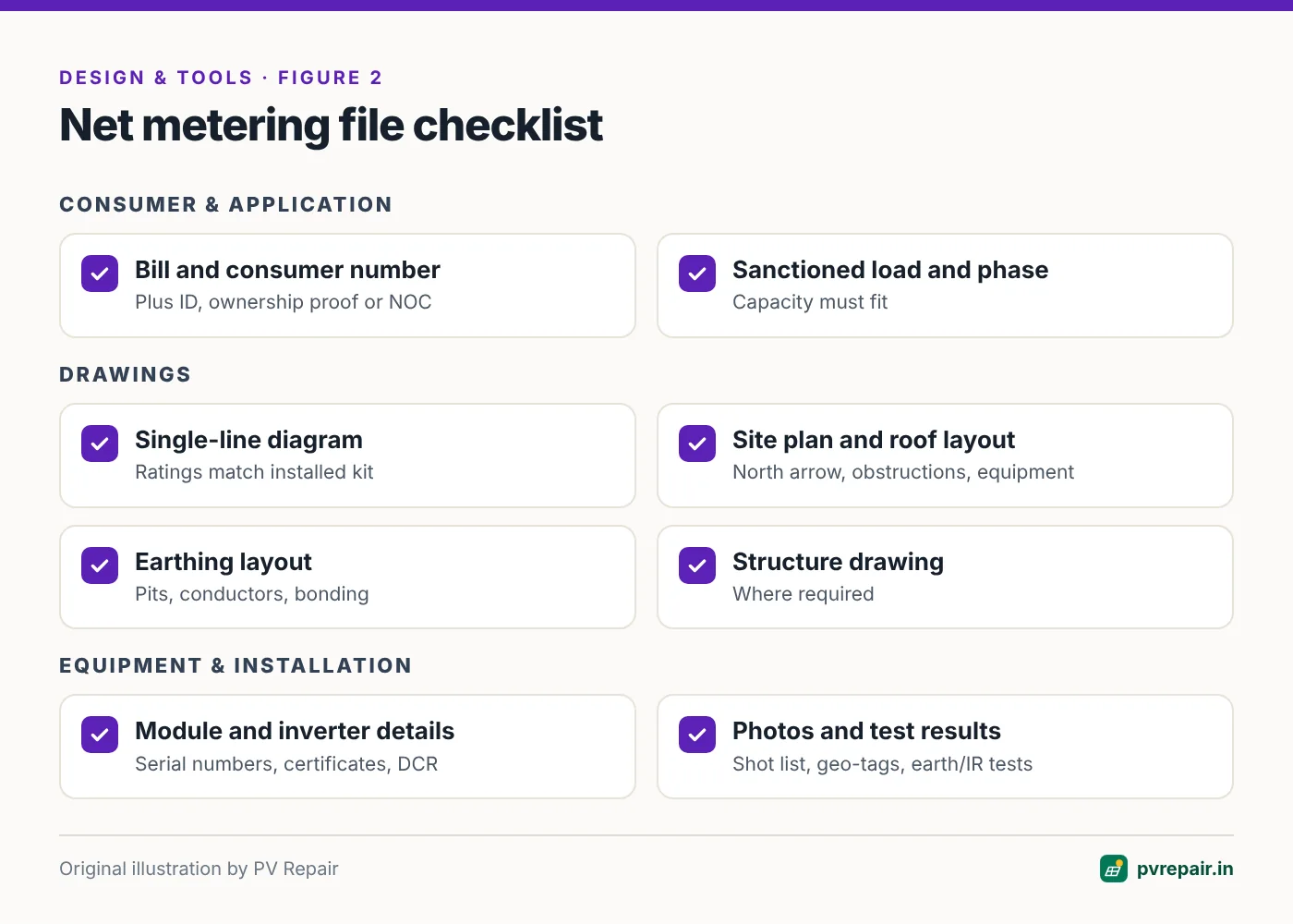
Consumer and application documents
- Latest electricity bill and consumer number.
- Identity proof and, where required, proof of ownership or a no-objection certificate from the owner or housing society.
- Sanctioned load and connection type (single- or three-phase).
- Bank details for subsidy transfer (residential).
- The feasibility approval, once issued.
Technical drawings
- Single-line diagram (SLD).
- Site plan / key plan showing the location of the property.
- Array layout drawing showing module positions on the roof.
- Earthing layout, and lightning protection layout where applicable.
- Structure drawing, where required (more often for elevated or C&I structures).
Equipment documents
- Modules: make, model, wattage, serial numbers, and certification as required by the scheme and DISCOM — typically IEC 61215 and IEC 61730 (or their BIS equivalents) and BIS registration. For subsidised PM Surya Ghar systems, DCR evidence for modules and cells.
- Inverter: make, model, rating, serial number and grid-compliance certification — commonly IEC 61727 (utility interface), IEC 62116 (anti-islanding) and IEC 62109 (safety), plus BIS registration.
- Cables, protection devices and structure: specifications as required.
- Warranty documents.
Installation and commissioning documents
- Work completion report or installation certificate from the vendor.
- Photographs of the installed system — often geo-tagged — showing modules, inverter, earthing and the meter location.
- Test results where required (for example earth resistance and insulation resistance).
- Commissioning report and joint inspection report.
- Net meter testing and installation records.
What a good single-line diagram contains
The SLD is the heart of the technical file. It shows, on one page, how energy flows from the modules through the protection devices and inverter to the grid. A DISCOM engineer should be able to check it in a few minutes.
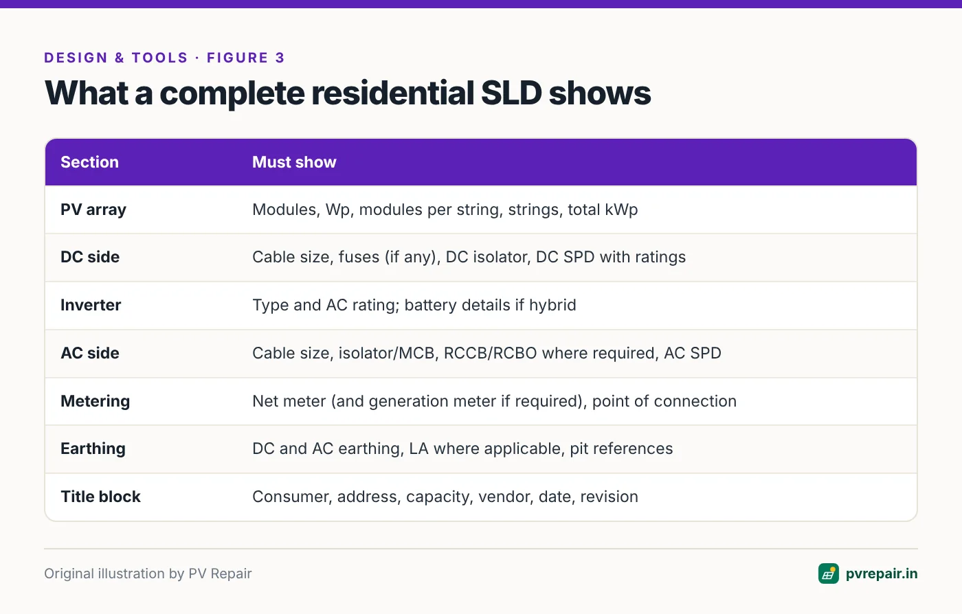
A complete residential SLD typically shows:
- PV array: number of modules, module wattage, modules per string, number of strings, and total DC capacity.
- DC side: DC cable size, string fuses (if used), DC isolator, and DC surge protection device with ratings.
- Inverter: make or type, AC rating, and whether it's grid-tie or hybrid (with battery details if hybrid).
- AC side: AC cable size, AC isolator or MCB, RCCB/RCBO where required, and AC surge protection.
- Metering: net meter (and solar generation meter if your DISCOM requires one) and the point of connection to the DISCOM supply.
- Earthing: separate earthing for DC and AC equipment and lightning protection as your design and DISCOM require, with earth pits identified.
- Title block: consumer name and number, address, capacity, vendor name, drawing date and revision.
Every rating on the SLD should match the equipment actually installed and the bill of materials. Most SLD rejections are inconsistencies, not engineering errors.
What a good site plan and layout drawing contain
- Site / key plan: the property's location — road, landmarks, plot boundary — so the inspector can find it, sometimes with a satellite image.
- Roof layout: roof outline with dimensions, module positions, obstructions (tanks, staircase rooms, parapets), walkways, and a north arrow.
- Equipment locations: inverter, DC and AC distribution boxes, earth pits, lightning arrester (if any), and the meter.
- Cable route: DC and AC cable routes from array to inverter to meter.
Inspectors use these drawings to check that the installation matches the application. A layout that shows 6 modules when 7 were installed, or an inverter in a different place, invites questions.
What a good earthing layout contains
- Earth pit locations, numbered, with type and approximate depth.
- Which equipment connects to which pit — module frames and structure, inverter, DC and AC SPDs, lightning arrester.
- Conductor material and size.
- Bonding method for module frames.
- Test points or inspection chambers.
See our guide to earthing and lightning protection mistakes for the engineering behind a good layout.
The most common reasons files are sent back
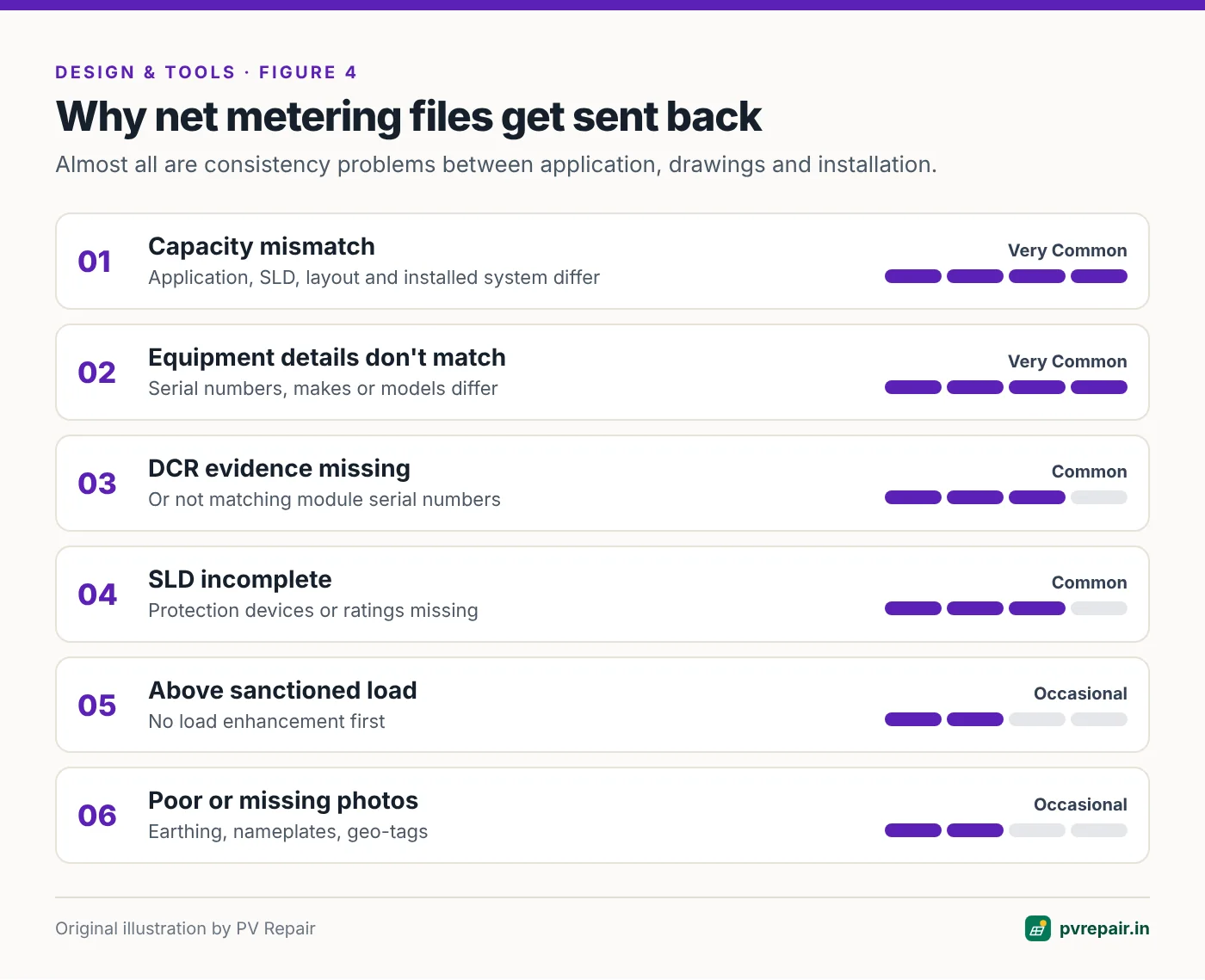
- Capacity mismatch between the application, the SLD, the layout and the installed system.
- Equipment details don't match — module or inverter serial numbers, makes or models differ from what was declared.
- DCR evidence missing or not matching module serial numbers on subsidised systems.
- SLD missing protection devices or ratings, or showing devices that weren't installed.
- Capacity above what the sanctioned load allows, without a load enhancement.
- Earthing details missing, or photos that don't show the earthing.
- Poor photographs — blurred, not geo-tagged where required, or missing key items.
- Missing inverter certification for grid compliance and anti-islanding.
Almost all of these are consistency problems. They happen when the application, drawings, BOM and installation are prepared by different people at different times.
A photo shot list that avoids resubmission
Photos are often the weakest part of a file. A fixed shot list, taken at the end of every installation, solves most problems:
- The whole array from a distance, showing the roof and surroundings.
- Close-ups of the module nameplates, readable, for a sample of modules.
- The mounting structure, showing anchoring and (for elevated structures) legs and bracing.
- The DC cable route and conduit or trays.
- The DC distribution box, open, showing fuses, isolator and SPD.
- The inverter nameplate and the inverter installed in place.
- The AC distribution box, open, showing MCB, RCCB/RCBO and SPD.
- Each earth pit and the earthing connections to the structure and equipment.
- The lightning arrester, if installed.
- The meter location, and the net meter once installed.
Enable location tagging on the camera if your DISCOM requires geo-tagged photos, and name files consistently so the inspector can find each item.
How to get approved first time
- Generate drawings from one design. When the SLD, layout, earthing drawing and BOM all come from the same source design, they stay consistent. Many EPCs do this with design software that produces a drawing set from the 3D model — see our comparison of 3D solar design software, including tools like SolarDraft and Solar Designer that output an SLD and site plan directly. Others maintain disciplined CAD templates.
- Freeze the design before procurement. Changes after drawings are submitted cause mismatches.
- Record serial numbers at installation, and cross-check them against DCR certificates and the declared equipment before upload.
- Photograph systematically using a fixed shot list: array, structure, inverter nameplate, DC and AC boxes, earthing pits and connections, meter.
- Keep a checklist per DISCOM, updated whenever their requirements change.
- Submit a trial file when you start working in a new DISCOM area, and ask for feedback before volume increases.
Frequently Asked Questions
What drawings are required for rooftop solar net metering in India?
Most DISCOMs require a single-line diagram, a site or key plan, and a roof layout drawing; many also ask for an earthing layout, and some for structure drawings. Requirements vary by state, so check your DISCOM's current checklist.
What should a solar single-line diagram include?
The PV array configuration, DC cables and protection devices, the inverter, AC protection devices, metering, the point of connection, earthing and a title block — with ratings matching the installed equipment.
Which certificates are needed for a solar inverter?
DISCOMs commonly require grid-compliance and safety certification such as IEC 61727, IEC 62116 (anti-islanding) and IEC 62109, along with BIS registration. Check your DISCOM's list.
Why was my PM Surya Ghar application rejected?
The most common reasons are inconsistencies: capacity or equipment that doesn't match between the application, drawings and installation; missing DCR evidence; missing protection devices on the SLD; or poor photographs. Fix the specific issue noted and resubmit.
Can design software generate DISCOM drawings automatically?
Several Indian design tools generate an SLD, site plan and layout drawings from the 3D design, which helps keep the file consistent. Always check the output against your DISCOM's format before relying on it.
Sources
- PM Surya Ghar national portal — pmsuryaghar.gov.in
- PM India, "Cabinet approves PM-Surya Ghar: Muft Bijli Yojana", February 2024 — pmindia.gov.in
- Mercom India, "Unverified DCR solar modules won't be accepted in government programs" — mercomindia.com
- Energetica India, "MNRE issues detailed clarification on ALMM List-II applicability across solar project categories" — energetica-india.net
Related guides
SolarDraft Review (2026): Features, Pricing, Pros and Cons for Indian Solar EPCs
An independent review of SolarDraft, the browser-based 3D solar design, proposal and CRM software for Indian EPCs — what it does well, where it falls short, what it costs, and who should choose an alternative.
Solar String Sizing Calculator for India: Cold Voc, Hot Vmp and Modules per String
Free solar string sizing calculator for Indian conditions. Enter module and inverter datasheet values to find the safe range of modules per string — checked against cold-morning Voc, hot-afternoon Vmp and inverter current limits — with the method explained.
Solar Designer Review (2026): 3D Rooftop Design, DISCOM Drawings and BOM for Indian EPCs
An independent review of Solar Designer (solardesigner.in), the browser-based 3D rooftop solar designer that produces a full drawing pack, SLD and bill of materials — strengths, limitations, and who should choose an alternative.