How to Test a Solar String with a Multimeter: Voc, Isc, Polarity and Insulation Checks
A safe, step-by-step method for testing solar PV strings — calculating expected Voc for temperature, checking polarity, measuring current with a DC clamp, comparing strings and recording results like a professional.
String testing is the foundation of almost every solar fault diagnosis. Whether you're commissioning a new system, chasing a low generation complaint, finding a failed bypass diode or tracing an open circuit, the same few measurements — open-circuit voltage, operating current, polarity and insulation resistance — tell you most of what you need to know.
This guide is written for trained technicians and serious students of PV. It explains the measurements, the safety precautions, how to correct for temperature, and how to interpret results. If you're a homeowner, use it to understand what your technician should be doing — but leave the testing to qualified personnel.
This is hazardous work
PV strings operate at up to 1000–1500 V DC and cannot be switched off at the modules in daylight. DC arcs can be sustained and cause severe burns. Use instruments rated CAT III 1000 V DC or higher (CAT III 1500 V for 1500 V systems), insulated test leads with shrouded probes, insulated gloves and eye protection. Never disconnect a connector under load. If you're not trained, don't do it.
What you need
- Multimeter rated CAT III 1000 V DC (or 1500 V as required), with a DC voltage range above the maximum string voltage.
- DC clamp meter for measuring current without breaking the circuit. Many modern clamp meters measure DC current accurately.
- Insulation resistance tester for insulation checks.
- PV test leads or adapters that allow safe connection to MC4-type connectors without improvised probing.
- Irradiance meter (or a reference cell) and infrared thermometer to record conditions.
- Module and inverter datasheets and the site's string layout.
- A test record sheet — on paper or a tablet.
Dedicated PV testers combine Voc, Isc, insulation resistance and irradiance measurements in one instrument and are standard for commissioning to IEC 62446-1. A multimeter and clamp meter can do most of the job for troubleshooting.
The four core measurements
1. Polarity
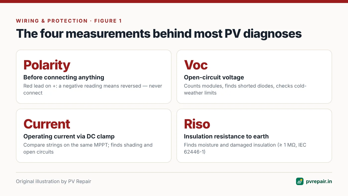
Before connecting any string to an inverter, combiner box or fuse holder, confirm its polarity. Reverse polarity can damage inverters and, on paralleled strings, cause large reverse currents. With the string isolated, measure voltage with the red lead on the conductor labelled positive. A positive reading confirms correct polarity; a negative reading means the labels or connections are reversed.
2. Open-circuit voltage (Voc)
Voc is measured with the string disconnected from any load (inverter DC isolator OFF, or string fuse open). It tells you:
- Whether all modules are connected (the string's Voc is the sum of its modules).
- Whether any bypass diodes have failed short (each one removes about a third of a module's Voc).
- Whether the string length is as designed.
- Whether cold-weather Voc is close to the inverter limit (see PV overvoltage).
3. Current (Isc or operating current)
Short-circuit current (Isc) is measured by deliberately short-circuiting the string through a suitably rated switch or test instrument. This is standard in commissioning with purpose-built PV testers, but shorting a string with improvised methods is dangerous.
For troubleshooting, it's usually safer and just as informative to measure operating current with a DC clamp meter while the inverter is running, and compare strings on the same inverter or MPPT. Strings in the same orientation and conditions should carry very similar currents.
4. Insulation resistance
Insulation resistance from PV+ and PV− to earth shows whether the string's insulation is intact. This is covered in depth in our isolation fault guide. IEC 62446-1 sets minimum values (1 MΩ for systems above 120 V), but compare strings with each other and with past results too.
Calculating the expected Voc
You can't judge a measured Voc without knowing what to expect. Module Voc depends mainly on cell temperature (and only weakly on irradiance above a few hundred W/m²).
Expected module Voc = Voc(STC) × [1 + β × (T(cell) − 25)]
Expected string Voc = expected module Voc × number of modules
Where β is the Voc temperature coefficient as a decimal (e.g., −0.0028 for −0.28 %/°C) and T(cell) is the measured module temperature. Measure the back of a module with an infrared thermometer, or estimate cell temperature from the front glass temperature — cells are usually a few degrees hotter than the glass surface.
Worked example
A string has 14 modules with Voc(STC) = 49.6 V and β = −0.28 %/°C. Measured module temperature is 52 °C.
- Correction: 1 + (−0.0028 × (52 − 25)) = 1 − 0.0756 = 0.9244
- Expected module Voc: 49.6 × 0.9244 ≈ 45.9 V
- Expected string Voc: 45.9 × 14 ≈ 642 V
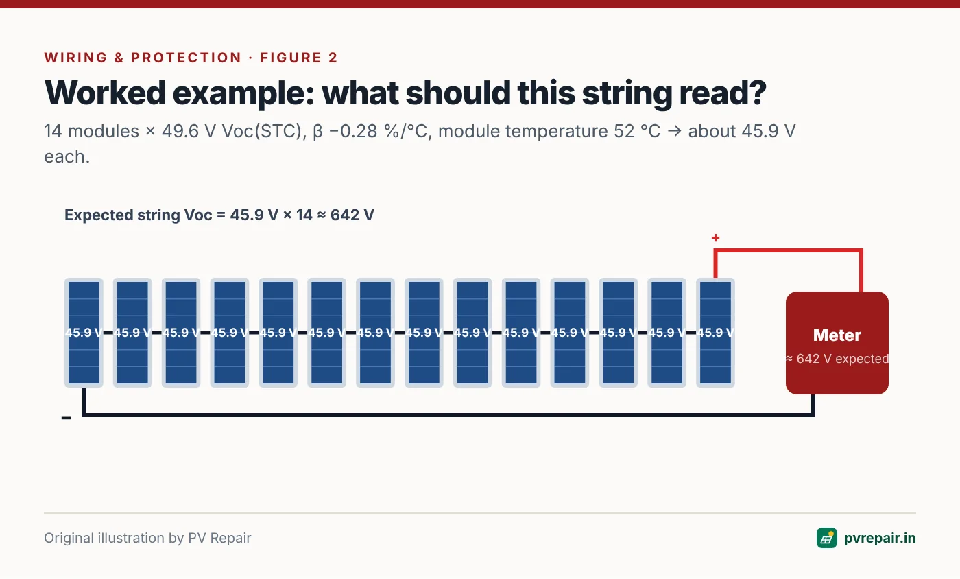
A reading of 640 V is healthy. A reading of about 627 V is roughly one-third of a module low — check for a shorted bypass diode. A reading near 597 V is about one module low — check for a missing or fully bypassed module, or a string that was built with 13 modules. Zero volts means an open circuit.
Compare strings, not just numbers
Temperature estimates and datasheet tolerances introduce uncertainty of a few percent. The most reliable method is to compare strings of the same length, orientation and module type measured within a few minutes of each other. They should agree within about 1–2%.
Step-by-step test procedure
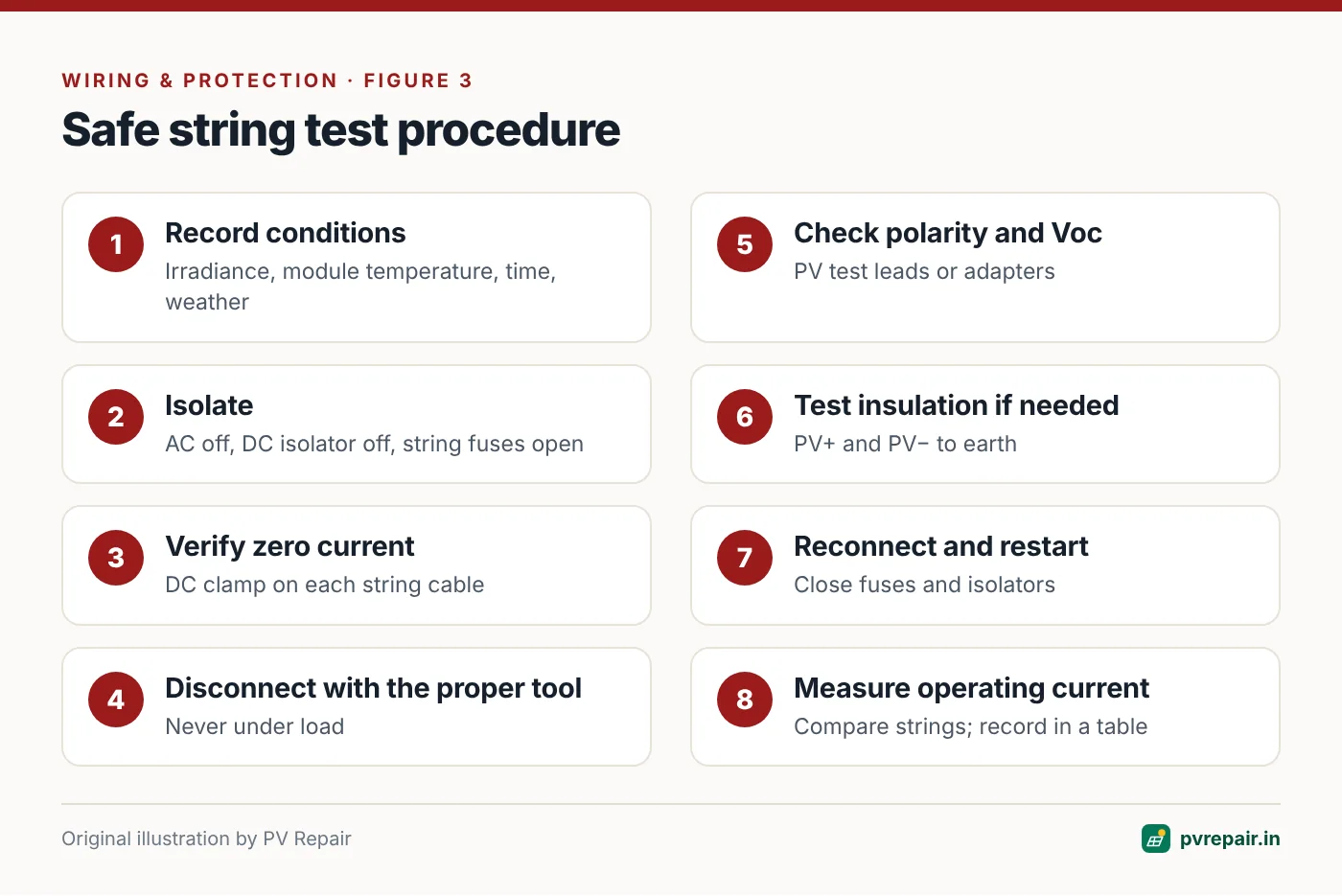
- Plan and record conditions. Note date, time, weather, irradiance and module temperature. Measurements should be taken in stable conditions — avoid fast-moving clouds.
- Isolate. Switch off the inverter's AC supply, then the DC isolator. Open string fuses or string isolators in the combiner box if fitted.
- Verify zero current. Use the DC clamp meter on each string cable to confirm no current is flowing before you disconnect anything.
- Disconnect the string at its connectors or fuse holder, using the proper unlocking tool.
- Check polarity and measure Voc with PV test leads or adapters.
- Test insulation resistance (PV+ to earth, PV− to earth) if required, following the tester's instructions.
- Reconnect all strings, close fuses and isolators, and restart the inverter.
- Measure operating current on each string with the DC clamp meter once the inverter is running at a stable power level. Compare strings.
- Record everything in a table with string identifiers matching the site layout.
Interpreting the results
| Observation | Likely cause | Next step |
|---|---|---|
| Voc ≈ expected, current ≈ other strings | Healthy string | Record as baseline |
| Voc low by ~⅓ module Voc | Shorted bypass diode | Module-by-module Voc |
| Voc low by ~1 module Voc | Missing/bypassed module, wrong string length | Count modules; module checks |
| Voc = 0 | Open circuit (connector, cable, fuse, module) | Trace the string |
| Negative Voc | Reversed polarity | Correct before connecting |
| Voc OK, current low | Shading, soiling, degradation, mismatch, PID | Inspect, I–V curve, thermal |
| Voc OK, current 0 with inverter running | Blown fuse or open connection on the inverter side | Check fuse and connectors |
| Insulation low | Moisture or insulation damage | See isolation fault guide |
Common mistakes when testing strings
- Testing in changing light. Moving clouds change current by the second. Compare strings only when irradiance is steady, or use an instrument that records irradiance at the same moment.
- Ignoring temperature. A healthy string can read 8–10% below datasheet Voc on a hot afternoon. Without temperature correction, technicians condemn good strings and miss real faults.
- Using the meter's 10 A current input on a string. It's not designed for this, the fuse may not interrupt a DC arc at string voltage, and the meter can be destroyed. Use a DC clamp.
- Probing into connector faces. Improvised probing inside MC4-type connectors damages contacts and risks slipping onto the wrong pole. Use PV test adapters.
- Forgetting to re-close fuses or isolators. A surprising number of "faults" after a service visit are strings left disconnected. Use a checklist and do a final current check on every string.
- Not recording the results. A measurement that isn't written down can't be compared next year.
Going further: I–V curve tracing
A multimeter gives you points; an I–V curve tracer gives you the whole curve. It reveals shading steps, mismatch, increased series resistance (from poor connections), shunt losses (from PID or cell damage) and a reduced fill factor, and it can translate results to STC for comparison with the datasheet. For commercial O&M and warranty claims, I–V tracing is the professional standard.
Building a baseline
The most valuable string test is the first one. A full set of commissioning measurements — Voc, current, insulation resistance and, ideally, I–V curves for each string — gives you a reference for every future diagnosis. If your installer didn't provide one, ask for a test report during the next service, and keep it with your system documents. Include it in your annual maintenance records.
Frequently Asked Questions
Can I test a solar string with a normal multimeter?
Only if the meter is rated for the voltage and category — CAT III 1000 V DC or higher for most string systems. Many cheap meters aren't safely rated. Use proper insulated test leads and PV adapters, and only if you're trained.
Is it safe to measure short-circuit current with a multimeter?
Generally no. Most multimeters' current ranges are limited to 10 A and aren't designed to interrupt DC arcs at string voltage. Use a DC clamp meter to measure operating current, or a dedicated PV tester for Isc.
Why is my measured Voc lower than the datasheet value?
The datasheet Voc is at 25 °C. On a sunny day, cells are often 45–65 °C, which lowers Voc by roughly 6–11%. Correct for temperature before deciding something is wrong.
How closely should strings match?
Strings with the same modules, length and orientation, measured at the same time, should typically agree within about 1–2% for Voc and a few percent for current. Larger differences deserve investigation.
Does irradiance affect Voc?
Only slightly, once irradiance is above a few hundred W/m². Voc is mainly affected by temperature. Current, on the other hand, is almost proportional to irradiance.
Related guides
Rodent, Monkey and Bird Damage to Solar Cables: Prevention and Repair
How rats, squirrels, monkeys and pigeons damage rooftop solar systems in India, the faults they cause, and proven prevention methods — conduit, cable trays, mesh skirts and bird deterrents — plus safe repair of chewed cables.
DC Arc Faults in Solar Systems: Warning Signs, Detection and Prevention
What DC arcs are, why they're more dangerous than AC arcs, the difference between series and parallel arcs, how arc fault detection (AFCI) works in inverters, and the installation practices that prevent arcing.
Solar Earthing and Lightning Protection: Common Mistakes and How to Fix Them
The earthing and lightning protection mistakes most often found on Indian solar rooftops — unbonded frames, shared or high-resistance earth pits, long SPD leads, missing separation distances — and how to correct each one.