MC4 Connector Failures: Why They Melt and How to Crimp Them Correctly
Why MC4-type solar connectors overheat, melt and let water in — cross-mating, poor crimping, loose nuts and strain — plus a step-by-step guide to correct assembly, testing and replacement.
The humble MC4-type connector is the most common connection point in any solar array. A 10 kW residential system may have 50 or more connector pairs; a 1 MW plant has many thousands. Each pair carries the full string current at up to 1000–1500 V DC, outdoors, for 25 years. When a connector fails, it can cause isolation faults, string outages, arcing and, in the worst cases, rooftop fires.
The vast majority of connector failures are not product defects but installation errors: mixing brands, using the wrong crimp tool, incomplete assembly, or mechanical strain. This guide explains how connectors fail, how to spot problems early, and how to assemble connectors properly.
Quick answer
MC4 connectors fail mainly because of cross-mating different brands, poor crimping (wrong tool or die, stripped length errors), incompletely tightened cable glands, cable strain, and water or dirt during assembly. These raise contact resistance or break the seal, causing heating, melting and leakage. Use matched connectors from one manufacturer, crimp with that manufacturer's specified tool, tighten glands to the specified torque, and protect connectors from strain and standing water.
How a connector works and why it heats up
An MC4-type connector has a metal contact (male pin and female socket) crimped onto the cable conductor, inside an insulating plastic housing with a seal and a gland nut. When mated, the contacts touch through a spring-loaded contact system (often a multi-lamella band), and the housings lock and seal together.
The contact resistance of a good, properly crimped and mated connector pair is very small — typically well under a milliohm. At 14 A, that's negligible heat. But heat at a contact rises with the square of current multiplied by the resistance. If contact resistance rises tenfold — due to a poor crimp, a mismatched contact, corrosion or contamination — so does the heat. Thermal cycling then loosens the contact further and accelerates corrosion. It's a runaway process that ends with melted housings.
The main causes of connector failure
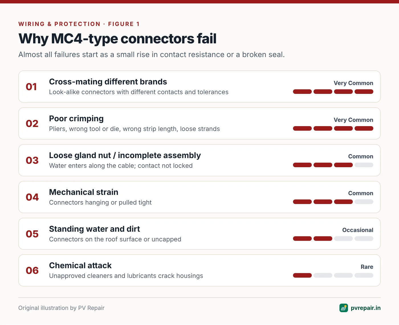
1. Cross-mating different brands
"MC4" originated as a specific product, and many manufacturers now make "MC4-compatible" connectors. They may look identical and even click together, but contact geometry, materials, plating and tolerances differ. Mating two different brands — for example, a module's factory connector with a different brand of field connector — is called cross-mating.
Cross-mated connectors can have higher contact resistance, poor sealing and different thermal behaviour. Standards for PV connectors (IEC 62852) test connectors as a matched pair from the same manufacturer; cross-mated pairs are generally not certified together unless the manufacturers have specifically tested and approved the combination. Many connector and module manufacturers explicitly state that cross-mating voids the warranty.
Same appearance isn't the same connector
Cross-mating is one of the leading causes of connector failures worldwide. When connecting to modules, use field connectors from the same manufacturer and type as the module's factory connectors, or a combination the manufacturers explicitly approve.
2. Poor crimping
The crimp joins the cable conductor to the metal contact. A good crimp is gas-tight: it deforms the conductor strands and contact barrel together so that no air or moisture can reach the interface. A poor crimp — loose, over-compressed, or made with the wrong tool — has higher resistance and can corrode.
Common crimping mistakes:
- Using generic pliers or the wrong brand's crimp tool.
- Using the wrong die size for the cable cross-section (4 mm² vs 6 mm²).
- Stripping too much or too little insulation.
- Missing strands outside the barrel or folded back strands.
- Contact not fully seated in the crimp tool locator.
- Using cable not specified for the connector (wrong outer diameter for the seal, or fine-stranded cable without the correct contact).
3. Loose gland nut or incomplete assembly
The gland nut compresses the cable seal around the cable jacket. If it's not tightened to the specified torque, water can enter along the cable. If the contact isn't fully pushed into the housing until it clicks, the connector may separate under strain or have poor contact.
4. Mechanical strain
Connectors pulled tight, bent sharply, or used to support cable weight experience stress on the contacts and seals. Long-term strain can partially separate the contacts or open the seal.
5. Water, dirt and standing water
Connectors assembled in dusty or wet conditions trap contamination inside. Unmated connectors left uncapped on the roof collect dirt and water. Connectors lying in water channels or on the roof surface sit in water after every rain, testing the seal continuously.
6. Chemical exposure
Some cleaning agents, oils, lubricants and plasticisers can attack connector plastics, causing stress cracking. Avoid unapproved chemicals near connectors.
Warning signs
- Discoloured, brown or melted connector housings.
- A burnt smell around the array.
- Warm connectors on a thermal image compared with others on the same string.
- Cracks in housings or deformed gland nuts.
- Connectors that rotate easily or appear partially separated.
- Green or white corrosion visible at the contacts when unmated.
- Electrical symptoms: isolation faults, string outages, arc fault alarms, or a string producing less current than its neighbours.
How to assemble MC4 connectors correctly
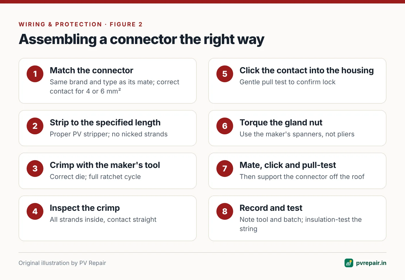
Always follow the connector manufacturer's instructions. A typical procedure:
- Confirm compatibility. Same manufacturer and type as the mating connector. Correct contact for the cable cross-section (e.g., 4 mm² or 6 mm²) and cable outer diameter range for the seal.
- Cut the cable cleanly and square.
- Strip the insulation to the length specified by the manufacturer (often around 7–8 mm, but check). Use a proper PV cable stripper to avoid nicking strands.
- Insert the conductor into the contact barrel. All strands must be inside; none bent back.
- Crimp with the manufacturer's crimp tool and the correct die position for the cross-section. The tool should complete its full ratchet cycle.
- Inspect the crimp. Strands visible through the inspection hole (if present), no loose strands, contact not bent.
- Push the contact into the housing until you hear or feel it click. Pull gently on the cable to confirm it's locked.
- Tighten the gland nut to the specified torque using the manufacturer's spanner tools, not pliers. Many manufacturers specify a torque or a "tighten until" mark.
- Mate the connectors until they click, and do a gentle pull test.
- Record the connector type, tool used and installer for quality records.
Reading a connector's ratings
Every PV connector has a datasheet, and a few numbers on it matter in the field:
- Rated voltage — typically 1000 V or 1500 V DC. It must be at least the maximum system voltage, including cold-weather Voc (see PV overvoltage).
- Rated current — depends on the cable cross-section and ambient temperature. Connectors are usually rated for well above typical string currents, but large-format and bifacial modules have pushed string currents higher. Check the rating at your site's maximum ambient temperature.
- Cable cross-section and outer diameter range — the contact must match the conductor size, and the seal must match the cable's outer diameter. A seal that's too large for a thin cable won't keep water out.
- IP rating — usually IP67 or IP68 when mated. Unmated connectors have no meaningful protection, which is why caps matter.
- Temperature range — the connector must tolerate rooftop temperatures behind modules, which can exceed 70 °C.
- Approved mating partners — the list of connectors the manufacturer has tested its product with. This is the definitive answer to the cross-mating question.
Testing connectors
- Visual inspection of every connector during commissioning and maintenance.
- Thermal imaging under load, comparing connector temperatures along a string. A connector significantly hotter than its neighbours needs attention.
- Insulation testing of strings, as covered in our string testing guide.
- Contact resistance measurement with a micro-ohmmeter is used in some quality programmes for high-value plants.
Replacing a failed connector
Never disconnect under load
MC4 connectors are not designed to break DC current. Disconnecting under load can draw a sustained arc. Always switch off the inverter and open the DC isolator or string fuses first, so no current is flowing, and work in low light or cover the modules when possible.
- Isolate the string as above and verify there's no current flowing with a DC clamp meter.
- Disconnect the damaged connector pair using the manufacturer's unlocking tool.
- Cut back the cable beyond any heat-damaged insulation.
- Fit both halves with new connectors from the same manufacturer (and the module's connector type, where connecting to a module). If the module's own factory connector is damaged, the module manufacturer's guidance applies.
- Insulation-test the string and record the results.
- Find out why the connector failed — strain, water, cross-mating — and correct the cause across the array, not just at the failed point.
Good practice for cable management
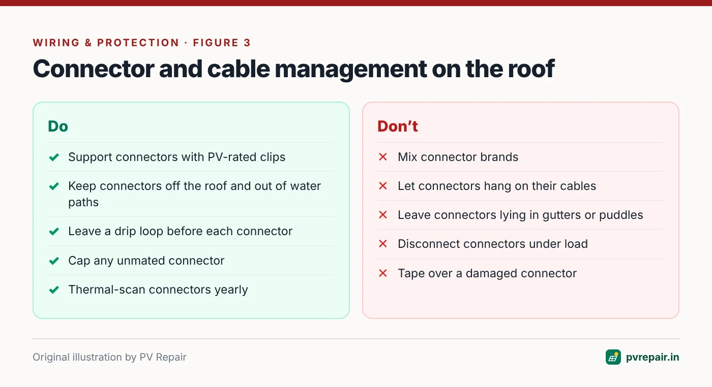
- Support connectors so they don't hang under their own weight or the cable's.
- Keep connectors off the roof surface and out of water paths.
- Use UV-resistant cable ties or clips designed for PV, and don't over-tighten them on connectors.
- Leave a small drip loop so water runs off before reaching the connector.
- Cap unmated connectors with matching caps.
- Avoid routing connectors where people walk.
Frequently Asked Questions
Can I connect different brands of MC4 connectors?
Only if both manufacturers have tested and approved the specific combination. Otherwise, cross-mating can cause higher resistance, poor sealing and overheating, and often voids warranties. Use matched connectors.
Why did my MC4 connector melt?
Most often because of high contact resistance from cross-mating, poor crimping or incomplete assembly, combined with high current and outdoor heat. Water ingress and corrosion can also increase resistance over time.
Can I crimp MC4 connectors with pliers?
No. Pliers can't produce the controlled, gas-tight crimp required. Use the crimp tool specified by the connector manufacturer, with the correct die for the cable size.
Should I use 4 mm² or 6 mm² cable?
It depends on string current, run length, voltage drop targets and installation conditions. Choose the connector contact that matches your cable size exactly, as specified by the manufacturer.
How often should connectors be inspected?
Inspect visually during every maintenance visit and thermal-scan them at least annually on commercial systems. Any discoloured or deformed connector should be replaced.
Related guides
Rodent, Monkey and Bird Damage to Solar Cables: Prevention and Repair
How rats, squirrels, monkeys and pigeons damage rooftop solar systems in India, the faults they cause, and proven prevention methods — conduit, cable trays, mesh skirts and bird deterrents — plus safe repair of chewed cables.
DC Arc Faults in Solar Systems: Warning Signs, Detection and Prevention
What DC arcs are, why they're more dangerous than AC arcs, the difference between series and parallel arcs, how arc fault detection (AFCI) works in inverters, and the installation practices that prevent arcing.
Solar Earthing and Lightning Protection: Common Mistakes and How to Fix Them
The earthing and lightning protection mistakes most often found on Indian solar rooftops — unbonded frames, shared or high-resistance earth pits, long SPD leads, missing separation distances — and how to correct each one.